An Introduction to the Whats, Whys, and Hows of DVB-T2 Scattered Pilot Patterns
Today’s most popular digital wireless systems – for example WLAN, digital terrestrial broadcast systems, 4G cellular networks, etc. – are all based on Orthogonal Frequency Division Multiplexing (OFDM).
In OFDM a large number of closely spaced orthogonal carriers are used to carry data on several parallel channels. A smaller number of the carriers are allocated to pilot tones which, among other things, can be used to estimate the channel.
The transmission protocol describes when and with what phase positions the pilot tones are transmitted. Based on that information the receiver can continuously estimate the quality of the channel over all frequencies. The performance of channel estimation in OFDM systems depends of course on the density of the predetermined scattered pilot symbols.
DVB-T uses the same static pilot tone pattern for all combinations of system parameters. DVB-T2 is more flexible and there are eight different pilot patterns, PP1-PP8, to select from.
The DVB-T2 scattered pilot pattern should be selected depending on what the expected channel type will be at the receiver. When selecting pilot pattern it is also very important to be aware of the trade-off between capacity and performance.
For a mobile or portable channel, where doppler performance is important, a pattern with a rapid repeat cycle should be selected. If Doppler performance is a dominant factor PP2, PP4 or PP6 should be considered. For those pilot patterns the scattered pilots will be repeated every second OFDM symbol. For PP1, PP3, PP5 and PP7 the scattered pilots will be repeated every fourth OFDM symbol.
If capacity is a dominant factor the least dense patterns should be selected. Pilot patterns with the greatest distances between pilots provide the highest capacity as more carriers are available to carry the data.
Required carrier to noise ratio (CNR) also depends on the selected pilot pattern. A denser pattern requires a higher CNR than those with a lower density. If the CNR is a dominant factor then lower density patterns, such as PP6 and PP7, should be considered.
The density of the scattered pilot patterns for PP2 and PP7 for DVB-T2 in SISO mode are presented in the two figures below.
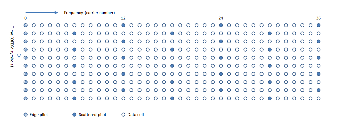
PP2 for DVB-T2 in SISO mode

PP7 for DVB-T2 in SISO mode
–
Thank you for reading this article about An Introduction to the Whats, Whys and Hows of DVB-T2 Scattered Pilot Patterns. If you have any questions about this article do not hesitate to contact me. Your feedback is welcome!
